Please follow this checklist to maximize the performance and reliability of your E-Drill System. The last section of this chapter shows typical damage which might be encountered.
1.1. General
- Replace any cracked or frayed cables.
- Tighten any loose connections.
- Check for leaks.
- Replace any cracked components.
1.2. Hand Tools
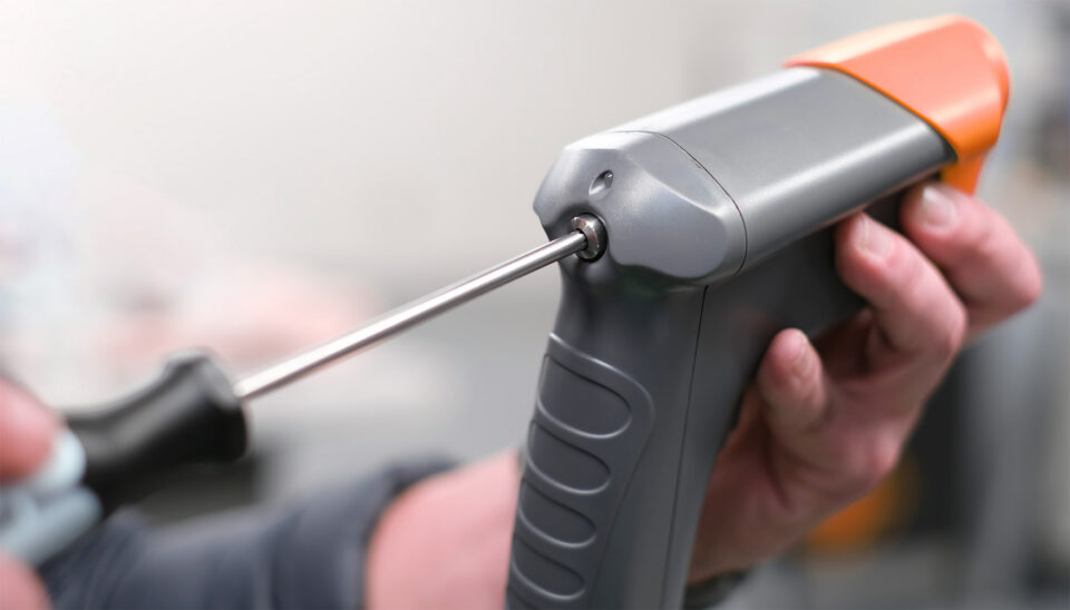
- Center Ground (CG) Mode – Check Ground Pin tightness using T20 Torx Key (Refer to Fastener Removal Guide section 6.6.).
- CG – check clear insulator sleeve on ground pin.
- CG – Before cutting, check spring loaded movement of Ground Pin against the fastener head.
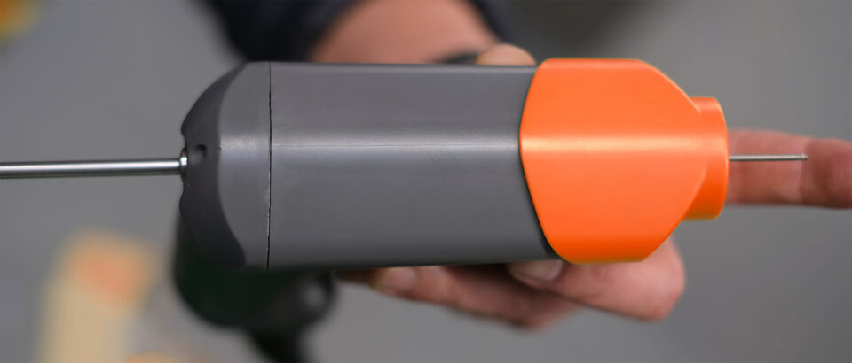
- Check correct size of electrode (refer to display) is installed and tightened with electrode wrench. Check electrode is not dented nor has uneven wear – dress or replace as necessary).
- Check all cables, strain reliefs, hoses, and connectors for damage.
1.3. Mobile Service Unit (MSU)
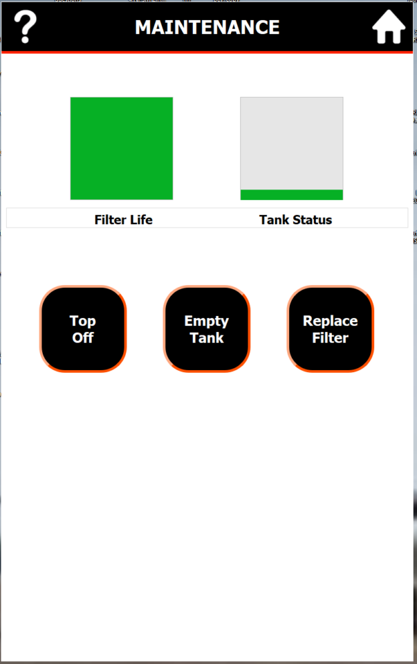
- Top-off before starting shift.
- Ensure MSU is upright and stable on a level ground with casters locked before use.
- Check the display for warnings (Sediment Tank or Filter).
- Ensure Hand Tool multi-connector bezel is tightened to detent. Check hoses are fully installed and seated.
- Check all cables, strain reliefs, hoses, and connectors for damage.
1.4. Adapters, Locators, and Electrode Guides
- Protruding head – Check bushing is snug fit around fastener head.
- Flush head visual – Check aperture ring is same size or slightly larger than fastener head, so head can be “sighted” for alignment.
- Flush head mechanical – Check size and correct type of Mechanical Locator. Check for wear or damage to locator tip. Check fastener recess is clean and paint-free, and locator fits into fastener head precisely.
- Adapter – Check thread fit to Hand Tool.
- Electrode Guide – Guide should be snug fit around correct size electrode. Check for wear and excessive play. Extract worn guides using the Guide Removal tool and replace.
- Check O-rings for wear or burn marks and replace as necessary (especially VFHL adapter red O-ring).
- Apply O-ring lube grease to adapter tri-wing feature (where it connects to hand-tool), and all adapter and locator O-rings.
1.5. Damage Examples
Cable connectors can receive abuse while in service.
The Hand Tool case is designed to withstand impacts, but if dropped on its electrode or drive tube mechanism, then damage may occur. For this reason, it is always important to keep an electrode and adapter on the hand-tool, even when not in use.
If a Hand Tool has been dropped and there is concern it may have been damaged, it may be checked by installing a new electrode, squeezing the trigger to ensure the electrode is at its full forward position, and measuring the protrusion of the electrode from the front of the chassis. A new electrode at the full forward position should protrude slightly under 1.5” from the front of the chassis.